


|
| electron Tube Data sheets |
|
|
| ||
|
| Bantam |
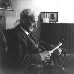
| The Bantam radio was build by my dad and I grew up with it. The photo shows our livingroom in Eindhoven in 1958 with my granddad and the Bantam. The Bantam was a DIY radio sold by Amroh. The design is very simple using ECH4 (2x), EBL1 and AZ1. As many other radios and other electronic instruments, my dad's Bantam did not survive my early hobby activities. |
| Here are the Description and Circuit diagram in Dutch (copyright Bureau Belper) |
| Original building instructions. (Added 2024-11-27) |
|
| December 2001 |
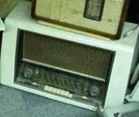
| I was looking to get one again for quite some time when, december 13 2001, I noticed something on the website of Mario Huizinga. He had a Blaupunkt radio for sale but on top of it was something that looked like a Bantam! (Photo below.) So I emailed him and he replied that indeed it probably was a Bantam. He lives not far from me and 4 days later we had a trade. I got the Bantam for a Philips tubetester he was looking for. Both parties happy! |
|
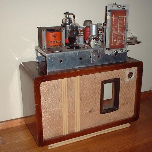
| The photo below shows the Bantam as I got it from Mario. There are still some parts missing. Modifications were made by a previous owner and I intend to restore it to it's original state as much as possible. Pity there was made a hole for an indicator tubem, which was not there originally. |

|
| April 2003 |
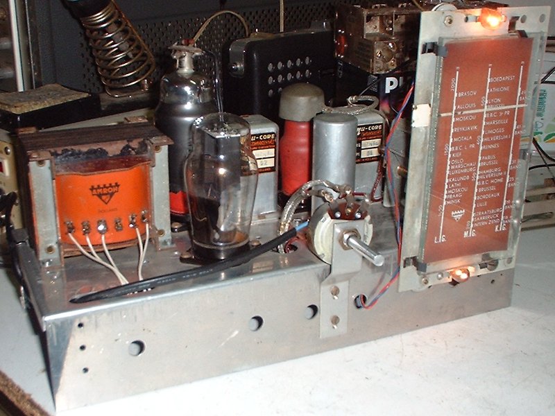
| Already April 20 2003! Finally I had some time to work on the Bantam. Earlier I found the missing mains- and output transformer. I got the mains transformer from Rob Hooft (Thanks Rob!!!) and I found the output transformer at the radio swapmeet which is held 4 times a year by the NVHR. There are still some parts missing: speaker and the 100Hz smoothing coil. But I decided not to wait for these items. I took out all none original circuit parts. Mainly the magic eye. But because the magic eye was added, a number of other changes were made too. I also noticed some errors: like one anode of the AZ1 was connected to a wrong pin meaning that the AZ1 always had operated as half-way rectifier. I left the parts that were mounted according to the original circuit in place. The chassis is a bit different from the one in the description. Probably a later, more universal model. So I placed the components where there was room on the contact strips that reside in the radio. When every thing had a place and was connected I turned it on and.... sound! The only thing was that the mains switch did not immediately make good contact. I had to operate it a few times and after a while it worked again. Then the 2nd ECH4 had a bad contact to the red shield. This causes the radio to generate awful noises. But I added an extra wire around the base and after that it worked perfectly! In stead of the coil there now is a 820 Ohm resistor which also works ok. Only the fact that the mains and output transformer are rather close together is causing some hum immediately after the Bantam is switched on, while the tubes are not yet operating. But when it comes on it's neglectable. There is one thing I have changed from the original circuit. As I have connected an external speaker of much better quality then a small internal radio speaker, I noticed the amplification of very low frequency was too much with S1 open (see schematic). So I placed an extra resistor of 6k8 across the switch (and C13) to have more feedback for frequencies below 200 Hz. The photo's below show the Bantam in operation condition! |
|
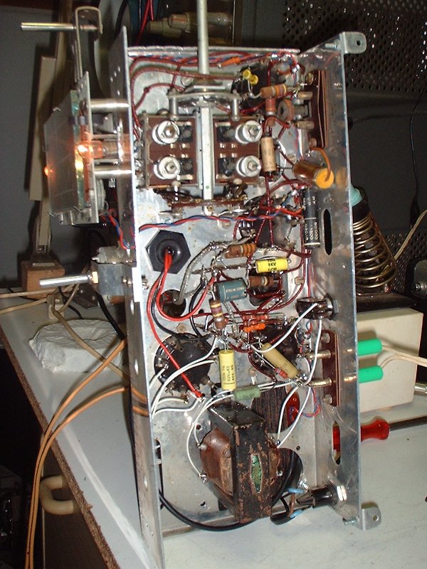
|
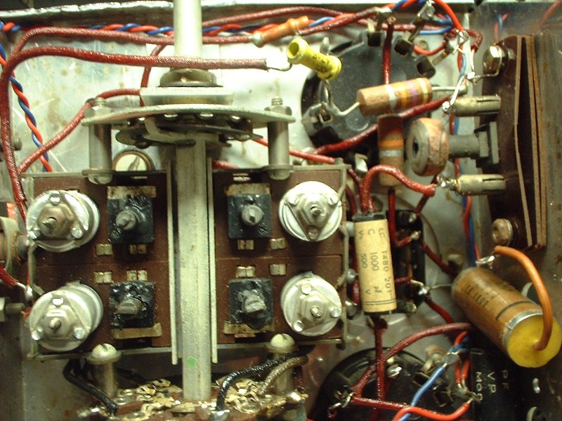
| This part is almost left untouched. |
|
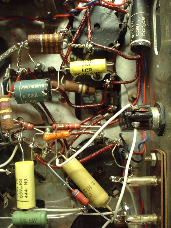
| This part is 'new'. |
|
|
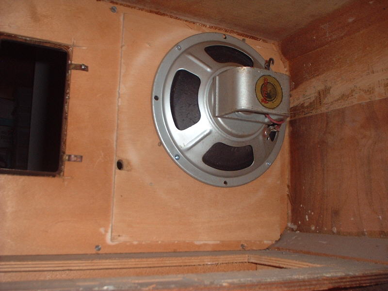
2003-12-13 : The photo below shows the speaker I found. Exactly the correct type!!! You can see that the person who build the radio used a different speaker. |
|